Overview
Matter aims to build a universal IPv6-based communication protocol for smart home devices. The protocol defines the application layer that will be deployed on devices as well as the different link layers to help maintain interoperability. The following diagram illustrates the normal operational mode of the stack:
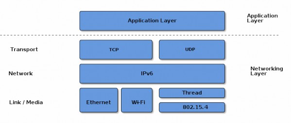
Figure 1. Application and Network Stack
Layered Architecture
The architecture is divided into layers to help separate the different responsibilities and introduce a good level of encapsulation amongst the various pieces of the protocol stack. The vast majority of interactions flow through the stack captured in the following Figure.
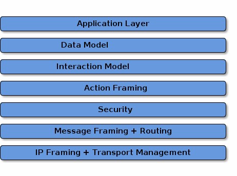
Figure 2. Layered Architecture
The Application layer corresponds to the high order business logic of a device. For example, an application that is focused on lighting might contain logic to handle turning on/off a light bulb, as well as its color characteristics.
The Data Model layer corresponds to the data and verb elements that help support the functionality of the application. The Application operates on these data structures when there is intent to interact with the device.
The Interaction Model layer defines a set of interactions that can be performed between a client and server device. For example, reading or writing attributes on a server device would correspond to application behavior on the device. These interactions operate on the elements defined at the data model layer.
Once an action is constructed using the Interaction Model, it is serialized into a prescribed packed binary format to encode for network transmission. This process is handled in the Action Framing layer.
An encoded action frame is then processed by the Security Layer: the message is encrypted and appended with a message authentication code. These actions ensure the data remain confidential and authentic between sender and receiver of the message.
With an interaction now serialized, encrypted, and signed, the Message Layer constructs the payload format with required and optional header fields, which specify properties of the message as well logical routing information.
After the final payload has been constructed by the Message Layer, it is sent to the underlying transport protocol (TCP or Matter’s Message Reliability Protocol) for IP management of the data.
Once the data is received on the peer device, it travels up the protocol stack, where the various layers reverse the operations on the data performed by the sender, to finally deliver the message to the Application for consumption.
In addition to the data flows captured above, this specification defines secure session establishment protocols based on operational certificates (see Section 4.13.2, “Certificate Authenticated Session Establishment (CASE)”), or passcodes (see Section 4.13.1, “Passcode-Authenticated Session Establishment (PASE)”), group communication (see Section 4.14, “Group Communication”), a bulk data transfer protocol (BDX) suitable for sending bulk data between Nodes, and provisions for defining manufacturer-specific protocols.
Network Topology
In principle, any IPv6-bearing network is suitable for Matter deployment, subject to supporting a few core IPv6 standards. In this version of the specification, we focus on three link layer technologies: Ethernet, Wi-Fi and Thread. We restrict the specification to the above so that the specification can suitably cover provisioning of these link layers, and so that the amount of testing in certification is suitably bounded.
Matter treats networks as shared resources: it makes no stipulation of exclusive network ownership or access. As a result, it is possible to overlay multiple Matter networks over the same set of constituent IP networks.
This protocol may operate in the absence of globally routable IPv6 infrastructure. This requirement enables operation in a network disconnected or firewalled from the global Internet. It also enables deployment in situations where the Internet Service Provider either does not support IPv6 on consumer premises or where the support proves otherwise limiting, for example, if the delegated prefix cannot accommodate all the networks and devices on premises.
This protocol supports local communications spanning one or more IPv6 subnets. Canonical networks supporting a fabric may include a Wi-Fi/Ethernet subnet, or one or more low power and lossy networks (LLN) subnets. In this version of the specification, Thread is the supported LLN standard.
Single network
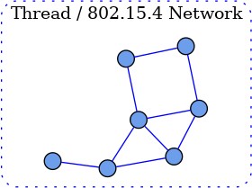
Figure 3. Single Thread network
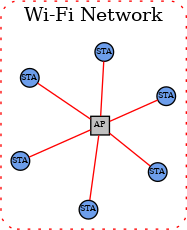
Figure 4. Single Wi-Fi network
In the single network topology, all Matter devices are connected to a single logical network. This could be a Thread/802.15.4 network, a Wi-Fi network or an Ethernet network. In the case of Wi- Fi/Ethernet, the network could in fact span multiple Wi-Fi and/or Ethernet segments provided that all the segments are bridged at the link layer. A Node is a single instance of a Matter device within a fabric, operationally available on an IP network.
Each Node in the single-network topology communicates with every other Node in the Fabric via a single network interface.
Star network topology
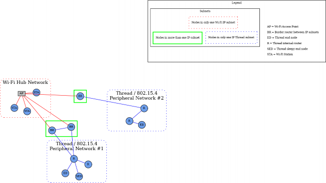
Figure 5. Star network topology
The star network topology consists of multiple peripheral networks joined together by a central hub network. The hub network will typically be the customer’s home network (Wi-Fi/Ethernet network), while the peripheral networks can be of any supported network type. A peripheral network MUST always be joined directly to the hub network via one or more Border Routers.
Architecturally, any number of peripheral networks may be present in a single Fabric, including multiple networks of the same type. Nodes MAY have interfaces onto any network (hub or peripheral), and MAY communicate directly to other Nodes on the same network. However, any communication that must cross a network boundary to reach its destination MUST flow through a Border Router.
This protocol places a set of requirements on the Border Router. These requirements pertain to address assignment, route assignment and advertisement, multicast support, and discovery proxying.
Note that in this version of the specification, Thread is the primary supported LLN. In many cases, customer installations will attempt to maintain a simple network topology, with a single Wi- Fi/Ethernet subnet, and a single Thread network. However, more than one Thread network is possible and supported.
To support home automation interoperability, this protocol supports the concept of bridging which makes available, through a data model node, devices implementing other home automation technologies, transports and link layers.
Scoped names
The Matter protocol explicitly supports multiple administrators, unrelated by any common roots of trust (multi-admin). This functionality is addressed via multiple fabrics and is enabled by the core aspects of name scoping (see below), and key considerations enabling multiple fabrics in onboarding, secure communication, and aspects of the data model (such as fabric-scoped data).
A Fabric is a collection of Matter devices sharing a trusted root. The root of trust in Matter is the Root CA that issues the NOCs which underpin node identities. Within the fabric, each node is uniquely identified by a stable Node ID. The scoped selection and allocation of these constructs within Matter ensures the uniqueness of identifiers and gives clear guidance on ownership and management of namespaces.
The operational root of trust — the root certificate authority (CA) as identified by its public key (Root PK) — is responsible for the allocation of correctly scoped fabric identifiers. The security of all public key infrastructures (PKI) depends on the private key of the CA being protected and neither guessable nor obtainable; that property, in turn, implies that the public key is globally unique. Within any root CA, the fabrics — identified by a 64-bit number — are unique. The uniqueness mechanism emerges from the collaboration of the commissioner and the root CA associated with that particular commissioner. Matter wraps the collaboration between the commissioner and its associated root CA and other possible data stores into a concept called the "administrative domain manager" (ADM). The algorithmic details and policies within the administrative domain manager are out of the scope of the specification as long as the allocation of all identifiers obeys the uniqueness and scoping criteria. Fabrics are uniquely identified by the tuple of their root CA’s public key and a Fabric ID. Similarly, within each fabric, the administrative domain manager is responsible for assigning a unique and stable Operational Node ID to every node.
The scoping strategy as outlined here ensures that each scoped identifier can be allocated solely by the entities responsible for the scoping, without consideration for collisions or forgeries. For example, two different CAs may allocate the same fabric identifiers and this would not create any
problems for the devices within the network. Scoped delegation of responsibility also provides for clear guidelines for the removal of specific identifiers.
A Matter device may be a member of multiple fabrics and thus have multiple associated node IDs. The scoping strategy also naturally lends itself towards unambiguous resolution of names and credentials and places a clearly defined responsibility for managing the namespaces on each fabric’s associated administrative domain manager service.
Prior to the first commissioning, such as in factory-reset state, a typical device contains no pre- allocated operational roots of trust, and no operational identities in the form of fabric IDs and node IDs. Yet, various interactions expect the fabric ID, or a node ID. These identifiers emerge in a number of internal constructs — from address discovery, through identifying secure sessions, to evaluating access control privileges. In order to regularize all interactions with the device and solve the bootstrapping problem, a special primordial fabric ID is reserved, and associates a set of initial access control privileges with any communication that would be associated with the initial commissioning sessions.
Identifiers
Fabric References and Fabric Identifier
As described above, a Fabric ID is a 64-bit number that uniquely identifies the Fabric within the scope of a particular root CA. Conceptually, the fully qualified fabric reference consists of the tuple containing the public key of the root certificate authority, and the Fabric ID. Because the fully qualified fabric reference is cumbersome to use, a number of mechanisms for compression of the reference are defined. The Fabric reference, in compressed form, is used during operational discovery to provide operational naming separation, a form of namespacing, between unrelated collections of devices.
Fabric ID 0 is reserved across all fabric root public key scopes. This fabric ID SHALL NOT be used as the identifier of a fabric.
A fabric is defined in the Data Model as a set of nodes that interact by accessing Data Model elements as defined in the Interaction Model (see Section 7.5, “Fabric”).
The layers below the data model, that convey data model interactions as messages, SHALL always indicate either the fabric associated with the message, or that there is no fabric associated with the message.
For example: A Data Model message that is conveyed over a message channel that uses the reserved fabric ID '0' does not have a fabric associated with it.
Vendor Identifier (Vendor ID, VID)
A Vendor Identifier (Vendor ID or VID) is a 16-bit number that uniquely identifies a particular product manufacturer, vendor, or group thereof. Each Vendor ID is statically allocated by the Connectivity Standards Alliance (see [CSA Manufacturer Code Database]).
The following Vendor IDs are reserved:
Table 1. Vendor ID Allocations
Range
Type
0x0000
Matter Standard
0x0001 - 0xFFF0
reserved for individual Manufacturer Codes as per CSA Manufacturer Code Database
0xFFF1
Test Vendor #1
0xFFF2
Test Vendor #2
0xFFF3
Test Vendor #3
0xFFF4
Test Vendor #4
All other allocations of Vendor ID are specified in CSA Manufacturer Code Database.

NOTE
The Test Vendor IDs are reserved for test and development by device manufacturers or hobbyists. Commissioners SHOULD NOT commission devices using one of these VIDs onto an operational Fabric under normal operation unless the user is made fully aware of the security risks of providing an uncertified device with operational and networking credentials.
Product Identifier (Product ID, PID)
A Product Identifier (Product ID or PID) is a 16-bit number that uniquely identifies a product of a vendor. The Product ID is assigned by the vendor and SHALL be unique for each product within a Vendor ID. Once a Product ID has been used, it SHALL NOT be reused by a different product type under the same Vendor ID. These Product IDs SHOULD NOT be specific to a unique physical device; rather they describe the product type, which might have many manufactured instances (e.g. multiple colors of the same product type).
A value of 0x0000 SHALL NOT be assigned to a product since Product ID = 0x0000 is used for these specific cases:
To announce an anonymized Product ID as part of device discovery (see Section 5.4.2, “Announcement by Device”).
To indicate an OTA software update file applies to multiple Product IDs equally.
To avoid confusion when presenting the Onboarding Payload for ECM with multiple nodes.
Group Identifier (GID)
A Group Identifier (Group ID or GID) is a 16-bit number that identifies a set of Nodes across a Fabric at the message layer (see Section 4.15, “Group Key Management”). A Group ID can further be bound to one or more Endpoints within each Node in the group at the interaction layer.
The Group ID space is allocated as described in Table 2, “Group ID Allocations”:
Table 2. Group ID Allocations
Range
Type
0xFF00 - 0xFFFF
Universal Group ID range reserved for static multicast and anycast identifiers
0x0001 - 0xFEFF
Application Group ID, assigned by fabric Administrator
0x0000
Null or unspecified Group ID
2.5.4.1. Universal Group ID
A Universal Group ID (UGID) is one that resides in the 16-bit subrange of Group ID that is reserved for groups that are common across this standard. These special multicast, groupcast, or anycast destinations are constant and known to all Nodes on any Fabric. The Universal Group ID space is allocated as described in Table 3, “Universal Group ID Allocations”:
Table 3. Universal Group ID Allocations
Range
Type
0xFFFF
All Nodes
0xFFFE
All non-sleepy Nodes
0xFFFD
All Proxies
0xFF00-0xFFFC
Reserved for future use
The Commissioner SHALL configure one or more shared keys for these groups on all Nodes within the Fabric. Because the keys and IPv6 multicast prefixes are different across Fabrics, Universal Groups only enable communication within a specific Fabric.
All Nodes Group
This group is used to message all Nodes in a Fabric.
All non-sleepy Nodes Group
This group is used to message all power-capable Nodes in a Fabric. Sleepy Nodes SHALL NOT subscribe to this group.
All Proxies Group
This group is used to discover Proxy Nodes during Section 9.15.4, “Proxy Subscriptions”.
Node Identifier
A Node Identifier (Node ID) is a 64-bit number that uniquely identifies an individual Node or a group of Nodes on a Fabric. The Node Identifier space is allocated as described in Table 4, “Node Identifier Allocations”:
Table 4. Node Identifier Allocations
Range
Type
0xFFFF_FFFF_FFFF_xxxx
Group Node ID
0xFFFF_FFFF_0000_0000 to
0xFFFF_FFFF_FFFE_FFFF
Reserved for future use
0xFFFF_FFFE_xxxx_xxxx
Temporary Local Node ID
0xFFFF_FFFD_xxxx_xxxx
CASE Authenticated Tag
0xFFFF_FFFC_xxxx_xxxx to 0xFFFF_FFFC_FFFF_FFFF
Reserved for future use
0xFFFF_FFFB_xxxx_xxxx
PAKE key identifiers
0xFFFF_FFF0_0000_0000 to
0xFFFF_FFFA_FFFF_FFFF
Reserved for future use
0x0000_0000_0000_0001 to
0xFFFF_FFEF_FFFF_FFFF
Operational Node ID
0x0000_0000_0000_0000
Unspecified Node ID
Node IDs are used for core messaging, within the internal APIs, within the data model, and to resolve the operational IPv6 addresses of Nodes (see Section 4.3.2, “Operational Discovery”).
The span of Node IDs from 0xFFFF_FFF0_0000_0000 to 0xFFFF_FFFF_FFFF_FFFF, as well as the value 0x0000_0000_0000_0000 are both reserved for special uses.
Operational Node ID
An Operational Node ID is a 64-bit number that uniquely identifies an individual Node on a Fabric. All messages must have an Operational Node ID as the source address. All unicast messages must have an Operational Node ID as the destination address.
While source or destination address MAY be elided from a message, it MUST remain unambiguously derivable from the Session ID.
Group Node ID
A Group Node ID is a 64-bit Node ID that contains a particular Group ID in the lower half of the Node ID.
Temporary Local Node ID
A Temporary Local Node ID is a 64-bit Node ID that contains an implementation-dependent value in its lower 32 bits. This allows implementations to keep track of connections or transport-layer links and similar housekeeping internal usage purposes in contexts where an Operational Node ID is unavailable.
PAKE key identifiers
This subrange of Node ID is used to assign an access control subject to a particular PAKE key as specified in Section 6.6.2.1.1, “PASE and Group Subjects”. An example usage would be to create an
ACL entry to provide administrative access to any commissioner communicating via a PASE session established with a particular pincode.
CASE Authenticated Tag
This subrange of Node ID is used to assign an access control subject to a group of peer nodes that share a single CASE session as specified in Section 6.6.2.1.2, “Subjects identified by CASE Authenticated Tag”.
Unspecified Node ID
The Unspecified Node ID (0x0000_0000_0000_0000) is a reserved value that never appears in messages or protocol usage. It exists to mark or detect the presence of uninitialized, missing, or invalid Node IDs.
IPv6 Addressing
This protocol uses IPv6 addressing for its operational communication. Node IDs and Fabric IDs are resolved to various types of IPv6 addresses [RFC 4291].
IPv6 Unicast Address
An IPv6 Unicast Address is one that uniquely identifies and addresses a single Node on an IPv6 network. A primary design goal for this standard is to allow Nodes to leverage native IPv6 technologies. As such, an operational IPv6 Unicast address that provides connectivity and routability between Nodes SHALL be used. This includes a global unicast address (GUA), a link-local address (LLA), or a unique local address (ULA).
IPv6 Multicast Address
An IPv6 Multicast Address is formed using Unicast-Prefix-based IPv6 Multicast Addresses [ RFC 3306]:
The first 12 bits are defined by [RFC 3306] and are 0xFF3.
The next 4 bits are "scop" (scope) and set based on [RFC 7346] Section 2 to:
Site-Local (0x5) - spans all networks in the Fabric, including Thread, Ethernet, and Wi-Fi.
The next 8 bits are reserved (0x00).
The next 8 bits are "plen", and set to 0x40 to indicate a 64-bit long network prefix field.
The network prefix portion of the Multicast Address is the 64-bit bitstring formed by concatenating:
0xFD to designate a locally assigned ULA prefix per [RFC 4193] Section 3.1
The upper 56-bits of the Fabric ID for the network in big-endian order
The 32-bit group identifier portion of the Multicast Address is the 32-bits formed by:
The lower 8-bits of the Fabric ID
0x00
The next 16-bits are the Group Identifier for the group, as specified in Group Identifier in big- endian order

FF35:0040:FD<Fabric ID>00:<Group ID>
An example of the site local scoped multicast address for a given <Fabric ID> and <Group ID>:

NOTE
though Site-Local scope is always used, the effective scope MAY be limited by setting the IPv6 hop count.
The Multicast Address formation ensures a low probability of a node receiving a multicast message it is not interested in. If a collision does occur on the multicast address (which requires two identical 64-bit Fabric IDs and two identical 16-bit Group IDs), processing of the message disambiguates which fabric and group is relevant by checking which operational group key leads to the message’s 64-bit MIC.
IPv6 Multicast Port Number
The IANA assigned port number is 5540.
IPv4 Coexistence
Matter devices SHALL be tolerant of IPv4 addresses and MAY ignore those addresses for the purposes of Matter operations.
Device identity
Each Matter device holds a number of certificate chains.
A Device Attestation Certificate (DAC) proves the authenticity of the manufacturer and a certification status of the device’s hardware and software. The Device Attestation Certificate is used during the commissioning process by the Commissioner to ensure that only trustworthy devices are admitted into a Fabric. The details of the device attestation process are captured in Section 6.2, “Device Attestation”.
Each Matter device is issued an Operational Node ID and a Node Operational Certificate (NOC) for that Operational Node ID. The NOC enables a Node to identify itself within a Fabric by cryptographically binding a unique Node Operational Key Pair to the operational identity of its subject, attestable through the signature of a trusted Certificate Authority (CA). Operational Node IDs are removed on factory reset or removal of Fabrics. A NOC is issued during the commissioning process of a device into a Fabric. These steps help to protect the privacy of the end-user and to adapt to different trust models.
The format of the Node Operational credentials and protocols for generating those credentials are detailed in Section 6.4, “Node Operational Credentials Specification” and Section 6.5, “Operational Certificate Encoding” sections.
Security
Matter deploys modern security practices to protect the Fabric. Matter designates a core set of security primitives detailed in Chapter 3, Cryptographic Primitives to provide comprehensive protection. Elliptic curve cryptography, based on the NIST P-256 curve (secp256r1) serves as the foundation for public key cryptography and digital signatures. Commonly available AES modes of operation have been selected to provide shared key cryptographic operations. In scenarios involving an out-of-band passcode-based authentication, Matter uses SPAKE2+, an efficient augmented PAKE algorithm.
The core cryptographic primitives form the basis of a number of complementary secure protocols used within Matter. All unicast Node-to-Node messages are secured, authenticated, and provide replay protection. Building on top of IPv6 multicast, Matter also provides group messaging facilities, useful for efficiently addressing on an LLN. The group messaging features prioritize low latency of packet processing.
Device Commissioning
Device commissioning (see Chapter 5, Commissioning) is the process of joining a device to a Fabric. The device being commissioned is referred to as the Commissionee and the device administering commissioning is referred to as the Commissioner. Device commissioning consists of the following steps:
Device discovery (see Section 5.4, “Device Discovery” and see Section 5.1, “Onboarding Payload”): The Commissioner discovers commissionable devices on network interfaces such as Bluetooth Low Energy, Wi-Fi, or other connected IP network. The Commissioner obtains the out- of-band secret (Passcode) from the commissionable device’s QR Code, Manual Pairing Code, NFC Tag or other means. This secret is used by Passcode-Authenticated Session Establishment (PASE) to establish a secure commissioning session. The order of discovering commissionable devices and obtaining the out-of-band secret from commissionable device is not critical.
Security setup with PASE (see Section 4.13.1, “Passcode-Authenticated Session Establishment (PASE)”): Establish encryption keys between the Commissioner and Commissionee using PASE. All messages exchanged between the Commissioner and Commissionee are encrypted using these PASE-derived keys. The process also establishes an attestation challenge used during the device attestation procedure.
Device attestation verification (see Section 6.2, “Device Attestation”): Commissioner establishes the authenticity of the Commissionee as a certified device, notifying the user if the device is not certified.
Information configuration (see Section 6.4, “Node Operational Credentials Specification”, Section 11.9, “General Commissioning Cluster” and Section 11.18, “Node Operational Credentials Cluster”): The Commissioner provides Commissionee with information such as regulatory domain, UTC time, Operational Certificate and network interfaces configuration.
Join network (see Section 11.8, “Network Commissioning Cluster” and Section 4.3.2, “Operational Discovery”): The Commissioner triggers the Commissionee to connect to the operational network unless the Commissionee is already on the operational network. The Node’s/Commissionee’s IPv6 address is then either used (if already known) or discovered (if not
known) by the Commissioner or Administrator.
Security setup with CASE (see Section 4.13.2, “Certificate Authenticated Session Establishment (CASE)”): Derive encryption keys used to establish secure communication between the Commissioner or Administrator and Node with CASE. All unicast messages between a Commissioner or Administrator and a Node are encrypted using these CASE-derived keys.
Commissioning complete message exchange (see Section 11.9, “General Commissioning Cluster”): A message exchange encrypted using CASE-derived encryption keys on the operational network that indicates successful completion of commissioning process.
A commissioner can reconfigure the Commissionee multiple times over the operational network after the commissioning is complete or over the commissioning channel after PASE-derived encryption keys are established during commissioning. The commissioning flows are described in Section 5.5, “Commissioning Flows”.
Sleepy End Device (SED)
One goal of this standard is to provide support for low energy Nodes running on limited power sources such as batteries or limited energy scavenging. The Sleepy End Device (SED) operating mode is defined to help extend and optimize battery lifetimes for such Nodes. The SED operating mode mirrors and aligns with Thread SED behavior, but may be leveraged over other supported IP interfaces, including Wi-Fi. The steady state behavior of a SED Node is to disable its IP interface (and underlying radio or link technology). A SED then periodically wakes to communicate with some infrastructure device in order to participate on the network. In the case of a Thread network (see [Thread specification]]), the infrastructure device is a parent Thread Router. For Wi-Fi, the access point provides the required infrastructure support. Two intervals are defined:
Idle mode, or slow-polling, sets the maximum time a SED will sleep before polling. This parameter affects both the minimum power consumption and maximum latency. The SLEEPY_IDLE_INTERVAL parameter communicates the maximum sleep interval of a node in idle mode.
Active mode sets the SED into a fast-polling interval for maximum responsiveness when the Node is engaged in ongoing communication, such as an active Exchange. The SLEEPY_ACTIVE_INTERVAL parameter communicates the maximum sleep interval of a node in active mode.
A SED SHALL indicate it is a sleepy device to peer nodes by setting its SLEEPY_IDLE_INTERVAL to a value greater than the default and advertising that value per [Discovery_SII].

NOTE
Because parent infrastructure devices have limited buffering space to cache messages on behalf of sleepy devices, SED communication patterns SHOULD be designed such that the SED is predominantly the initiator.
A Node determines whether it is in Active or Idle mode based on whether it has any outstanding Exchanges in the Message Layer. While there are Exchanges active, a node will remain in Active mode and poll at the fast-polling interval if it is a SED. Once all Exchanges are closed, a node SHOULD transition into Idle mode and poll at the slow-polling interval if it is a SED and the node has no other outstanding reasons for staying awake.
Data Model Root
Endpoint 0 (zero) SHALL be the root node endpoint. Endpoint 0 (zero) SHALL support the Root Node device type.
Stack Limits
System Model Limits
Access Control Limits

For example: A node that supports 6 fabrics must support at least 18 ACL entries, and if it supports N entries must enforce that any K fabrics together do not use more than N - 3*(6-K) entries.
A node SHALL guarantee that there are at least three Access Control Entries available for every fabric supported by the node.
Device types MAY impose additional constraints on the number of ACL entries that need to be supported.
Group Limits
A node SHALL support at least one group key per fabric for managing the IPK.
If the node implements one or more device types with support for the Groups cluster, the node SHALL additionally support the maximum number of the required groups as specified by all of these implemented device types.
A node SHALL support one IPv6 multicast group membership for every operational group it supports.
Interaction Model Limits
Read Interaction Limits
A server SHALL ensure that every fabric the node is commissioned into can handle a single Read Interaction from a client on that fabric containing up to 9 paths.
A server MAY permit Read Interactions even when there is no accessing fabric, subject to available resources (e.g over PASE).
Subscribe Interaction Limits
A publisher SHALL ensure that every fabric the node is commissioned into can support at least three Subscribe Interactions to the publisher and that each subscription SHALL support at least 3 attribute/event paths.
A server MAY permit Subscribe Interactions even when there is no accessing fabric, subject to
available resources (e.g over PASE).
Device type specifications MAY require a larger number of supported subscriptions or paths.
SUBSCRIPTION_MAX_INTERVAL_PUBLISHER_LIMIT defines the upper limit for the publisher-selected maximum interval for any subscription. This SHALL be set to 60 minutes.
The minimal supported capabilities, subject to the minimal constraints above, are reported in the CapabilityMinima attribute of the Basic Information cluster.
Invoke Interaction Limits
An Invoke Request action SHALL be limited to a single concrete command path.
Support for Invoke Interaction involving multiple paths or wildcard paths is optional and provisional in this version of the specification.
Parameters and Constants